
Treatment & installations · Ipswich & Suffolk
Treatment & installations — the work behind the reports
Photos taken on site during our own damp proofing and installation works across Ipswich, Suffolk, Essex and Norfolk. No stock images — this is our team fitting cavity drain membranes, waterproofing systems and replastering, start to finish.
19 years' experience · CSTDB & CSSW certified · All works guaranteed
On site
From our recent installations
Every photo below was taken during a real treatment or installation job. Ask us about any of them and we'll explain exactly what we installed and why.
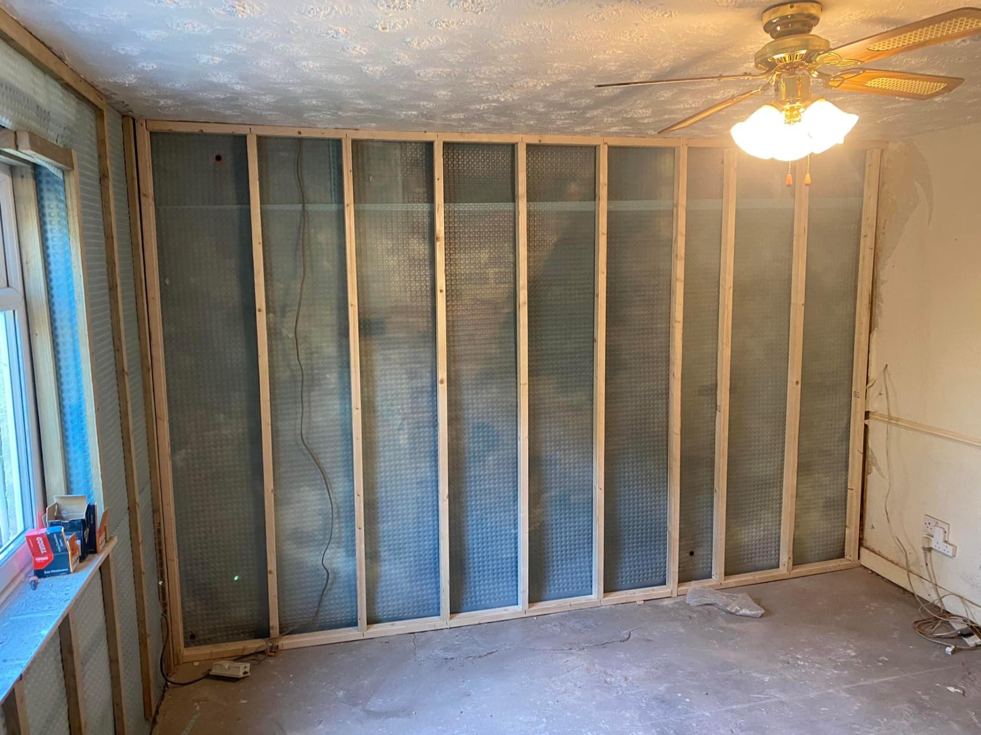
Cavity drain membrane with stud wall framework
Cavity drain membrane fixed across the wall with a treated timber stud framework built over it. The studs take the new wall boards while the membrane behind manages any moisture coming through the masonry.
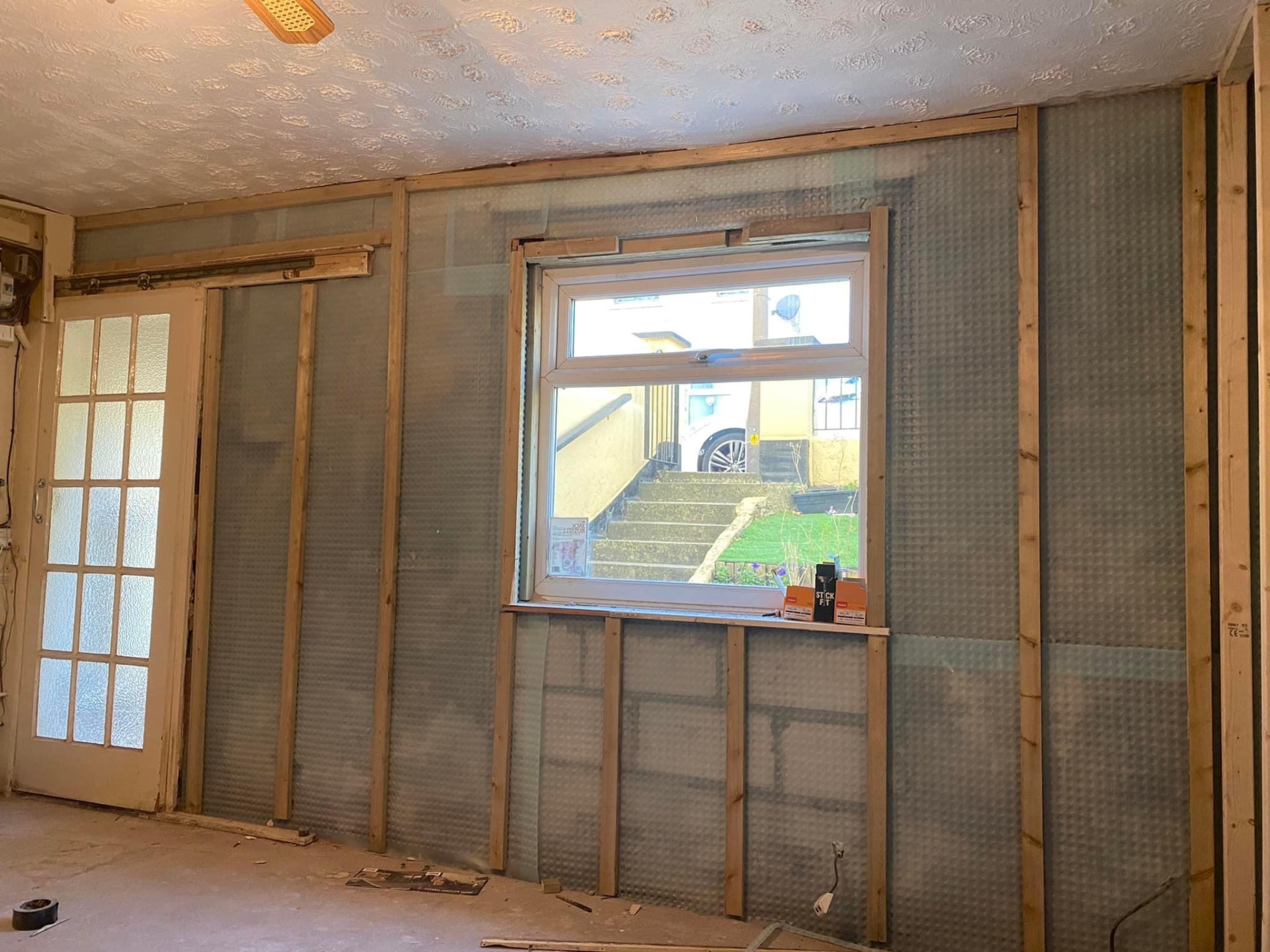
Membrane and battens around a window
The membrane system worked neatly around the window reveal with battens fixed over it, ready for the new wall lining. Every reveal and corner is detailed so the barrier stays continuous.
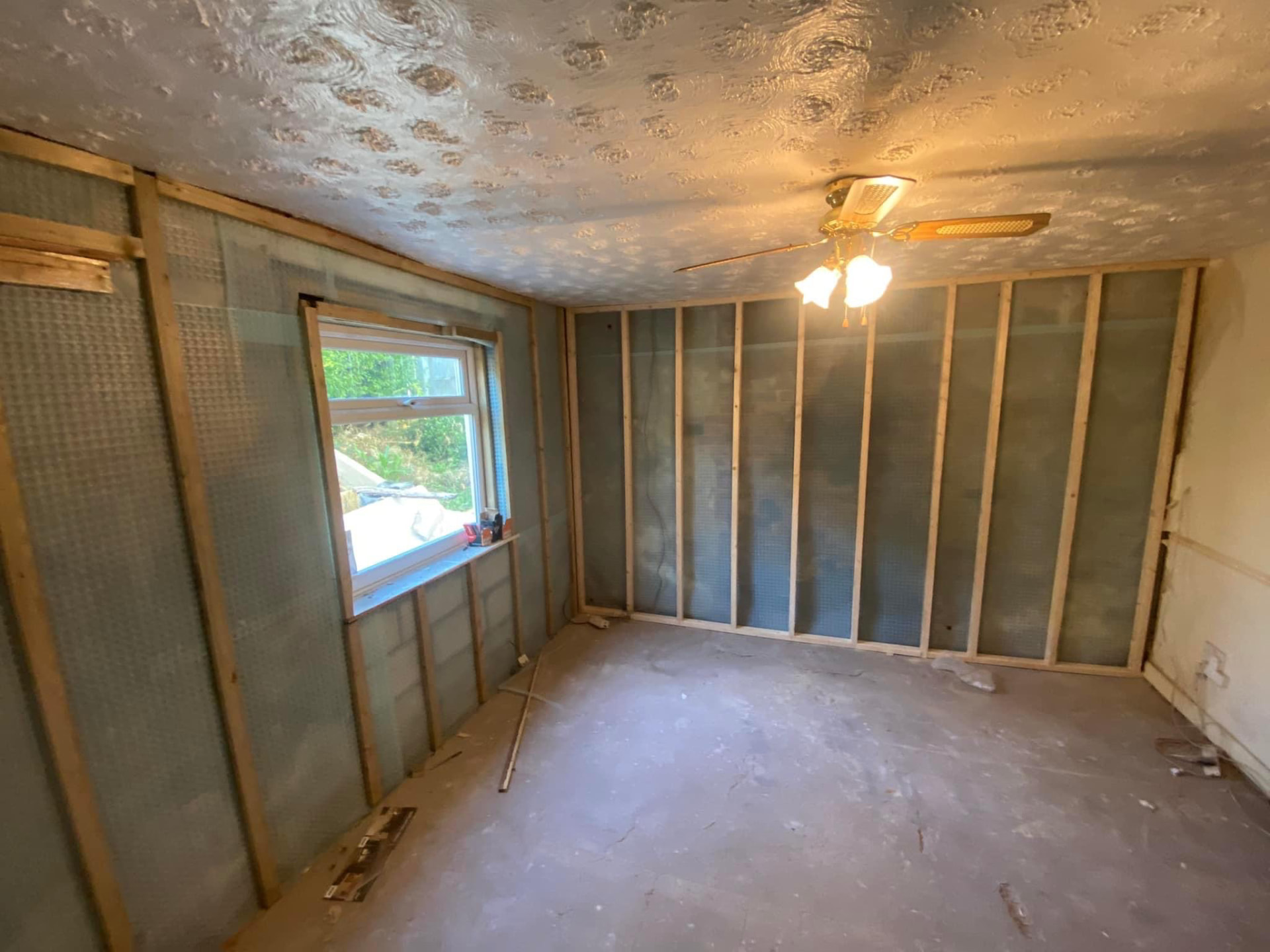
Full room membrane installation
A whole room lined with cavity drain membrane and studwork ahead of boarding and plastering — the walls are now isolated from the damp masonry behind.
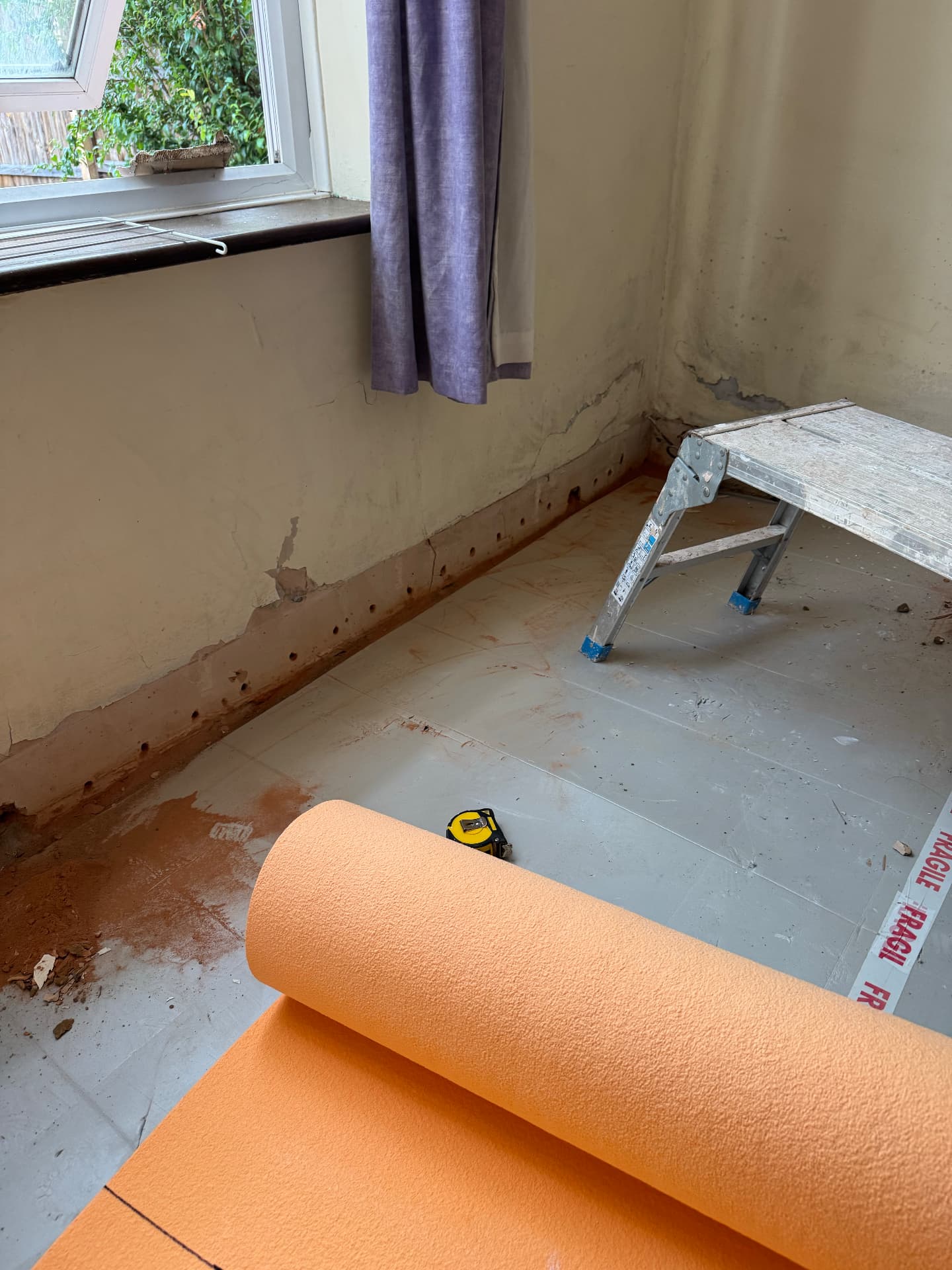
ISO Therm membrane measured and cut
ISO Therm thermal membrane rolled out and cut to size on site. The old damp plaster has been stripped back and the wall prepared ready for the membrane to be applied.
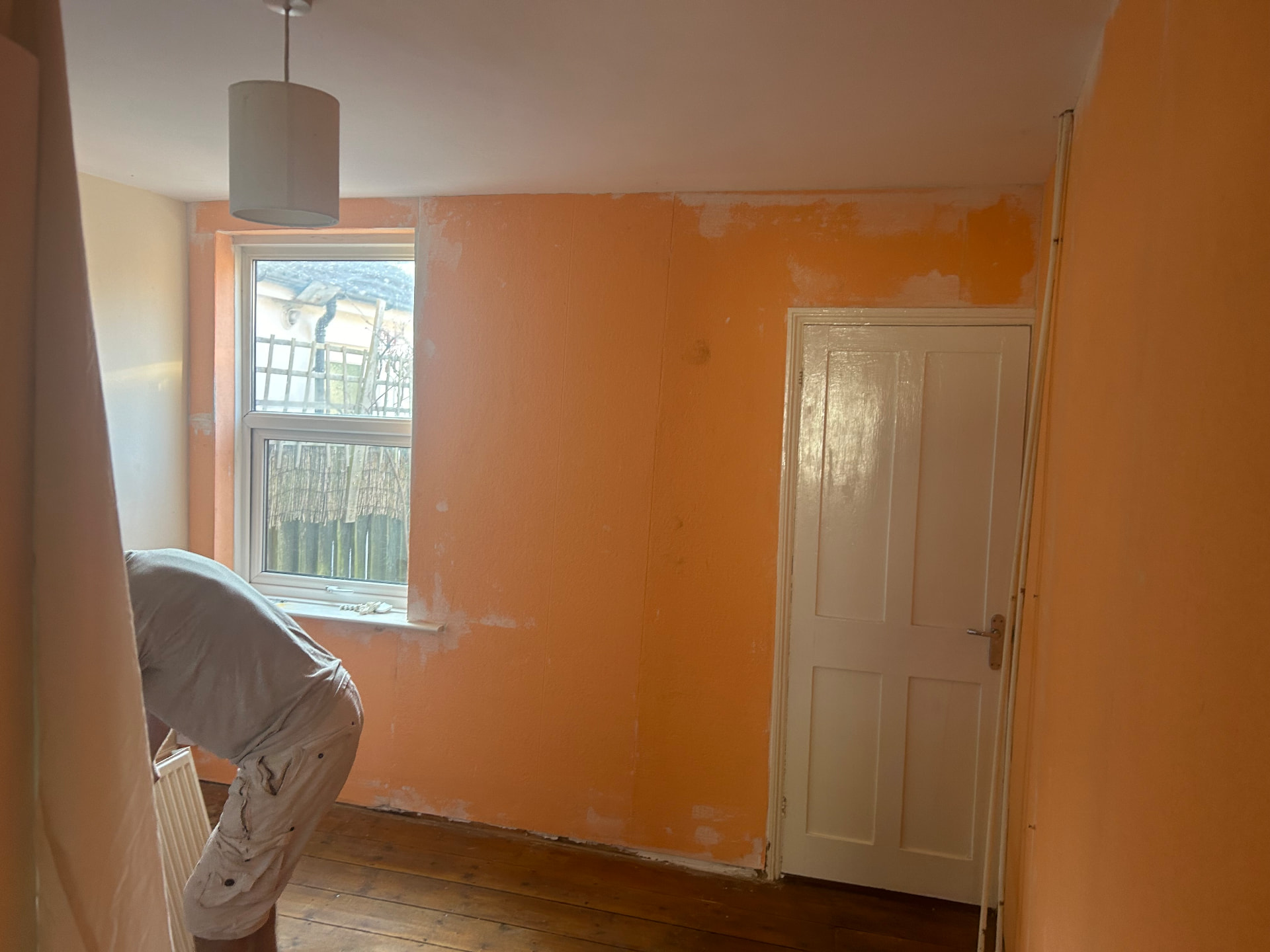
ISO Therm thermal membrane on the walls
ISO Therm thermal membrane applied across the walls. It warms the wall surface, which cuts down condensation and the mould that comes with it — ideal for cold external walls.
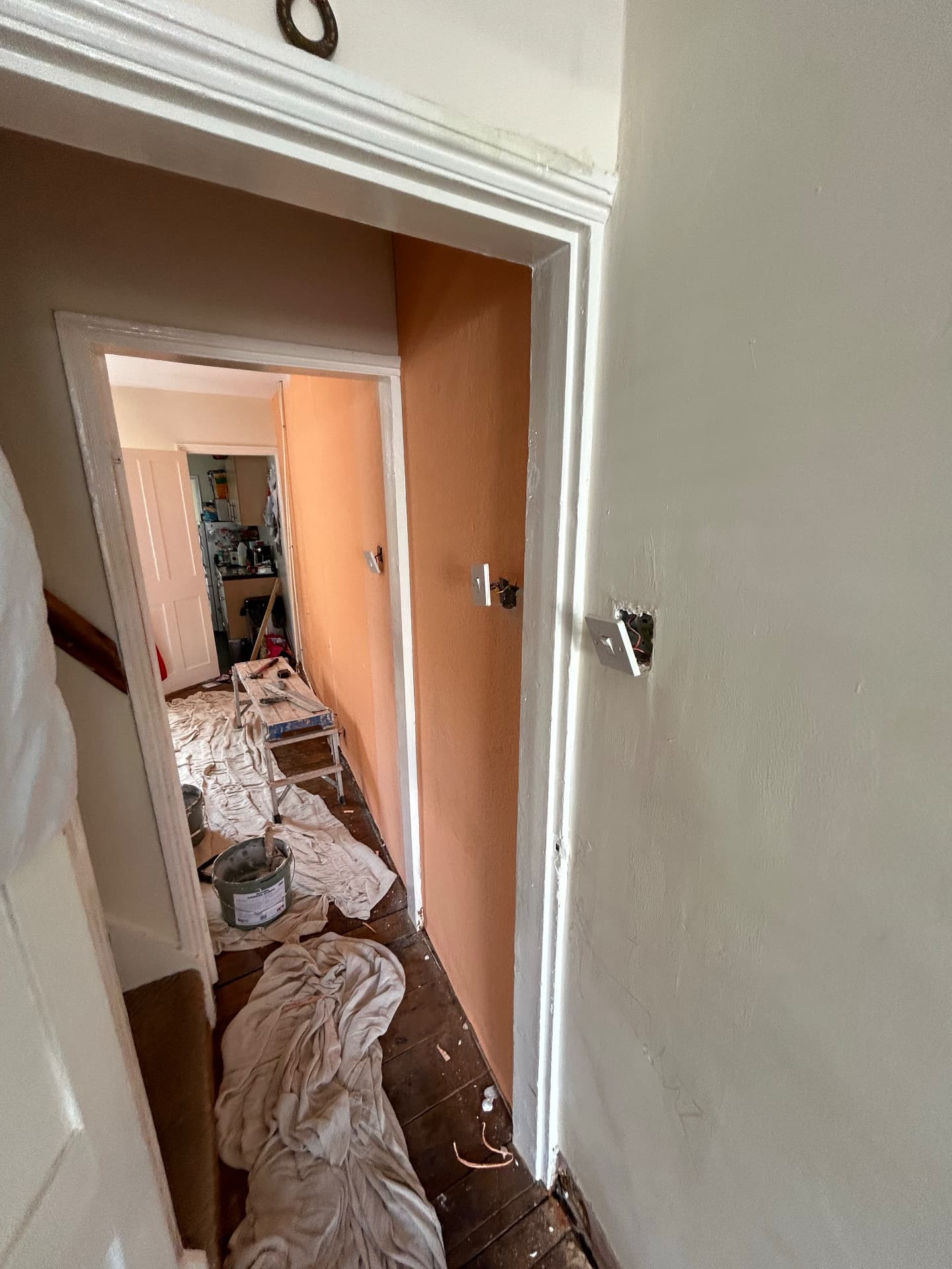
ISO Therm through the hallway
The thermal membrane carried through the hallway walls as part of the same installation, keeping the whole area protected against condensation.
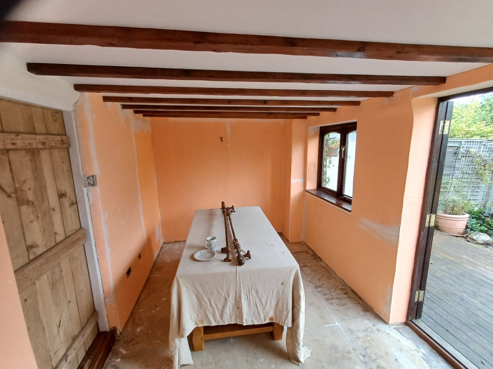
ISO Therm in a beamed room
ISO Therm applied to the walls of a room with exposed oak beams — a breathable thermal layer that suits older properties where the walls need to stay warm and dry.
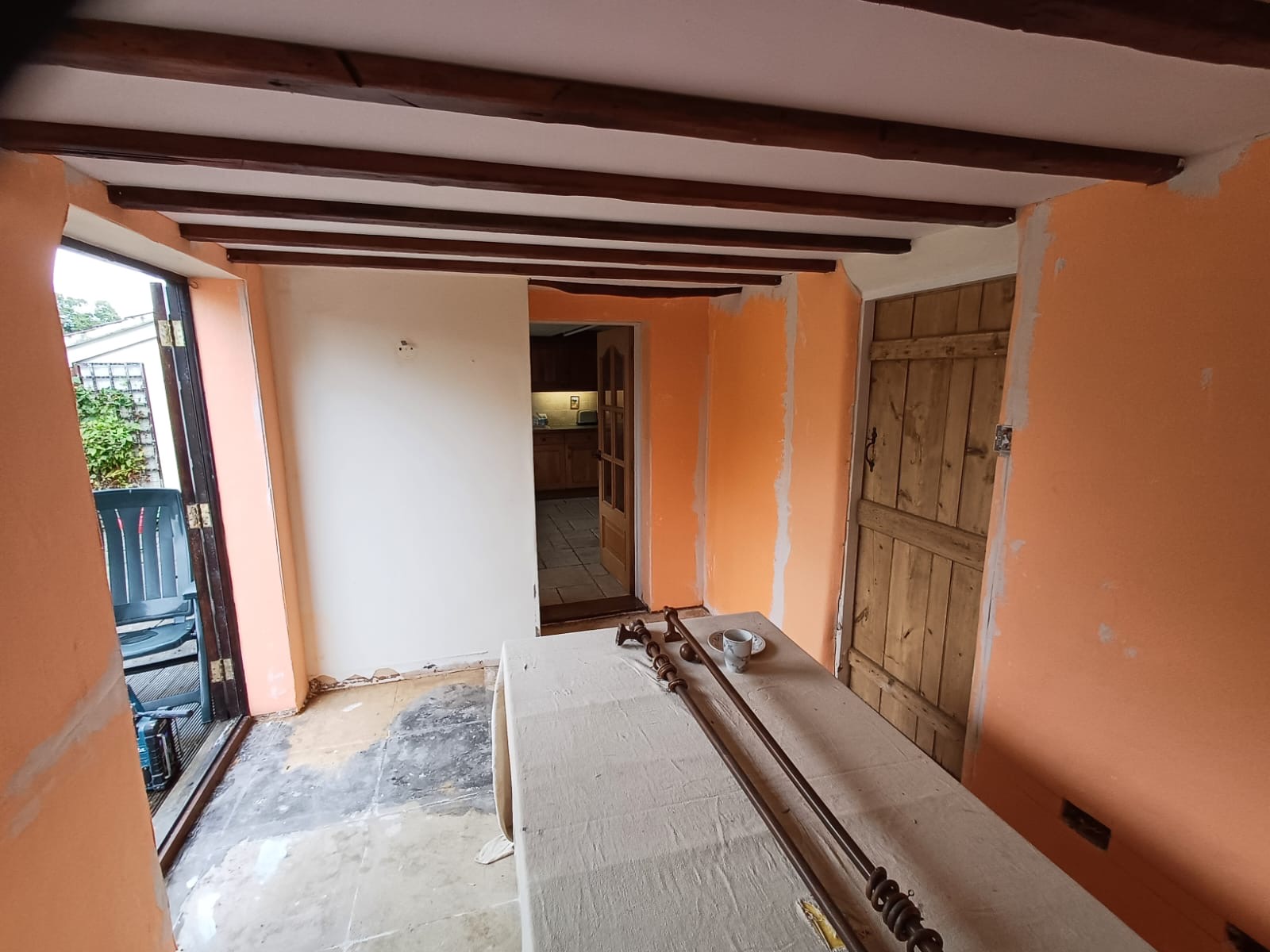
Membrane detailed around doorways
The membrane worked carefully around the doorway and openings, ready for the finishing plaster skim over the top.
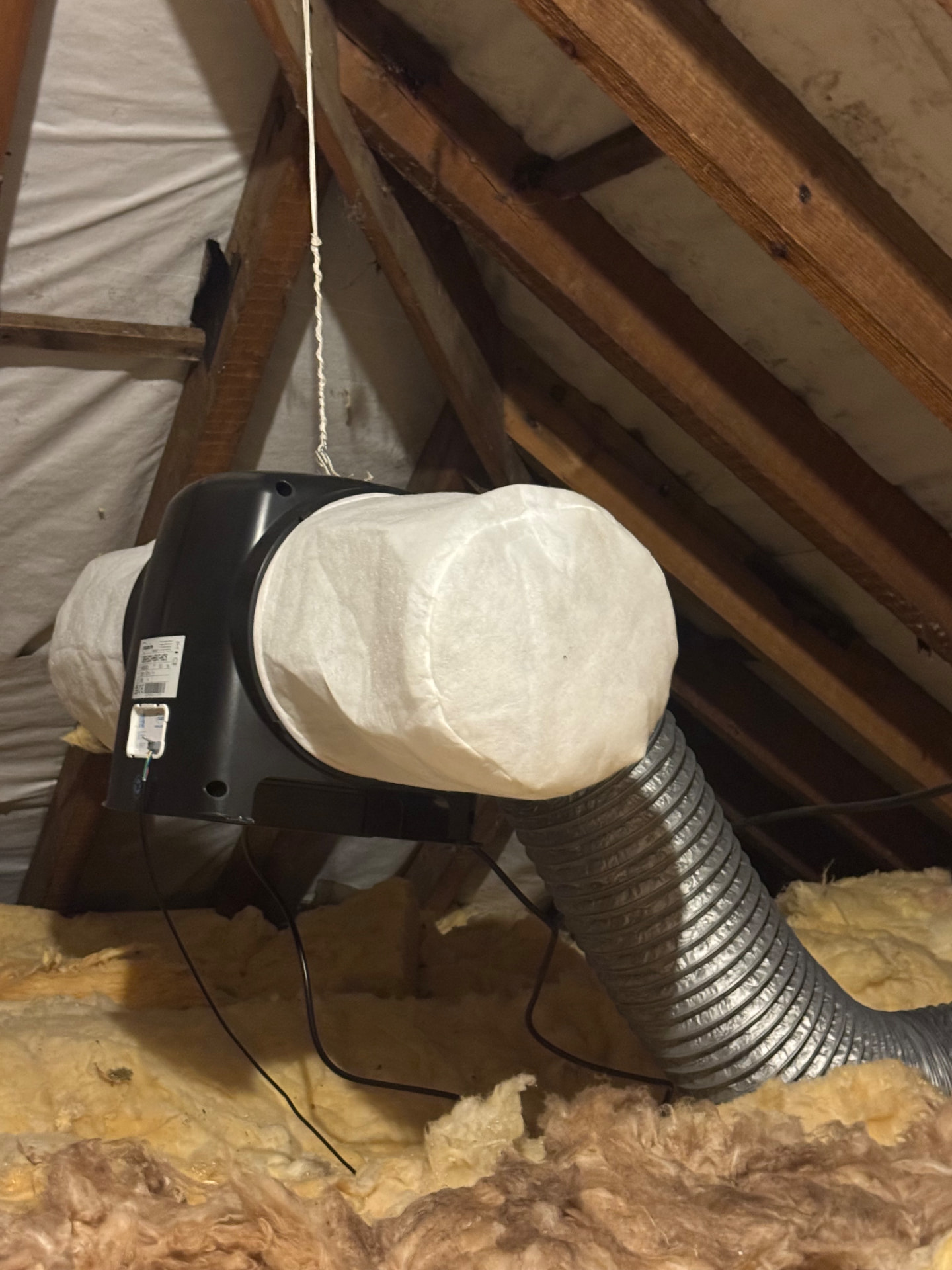
Positive input ventilation unit in the loft
PIV unit installed in the loft space to bring filtered fresh air into the home and reduce condensation and mould.
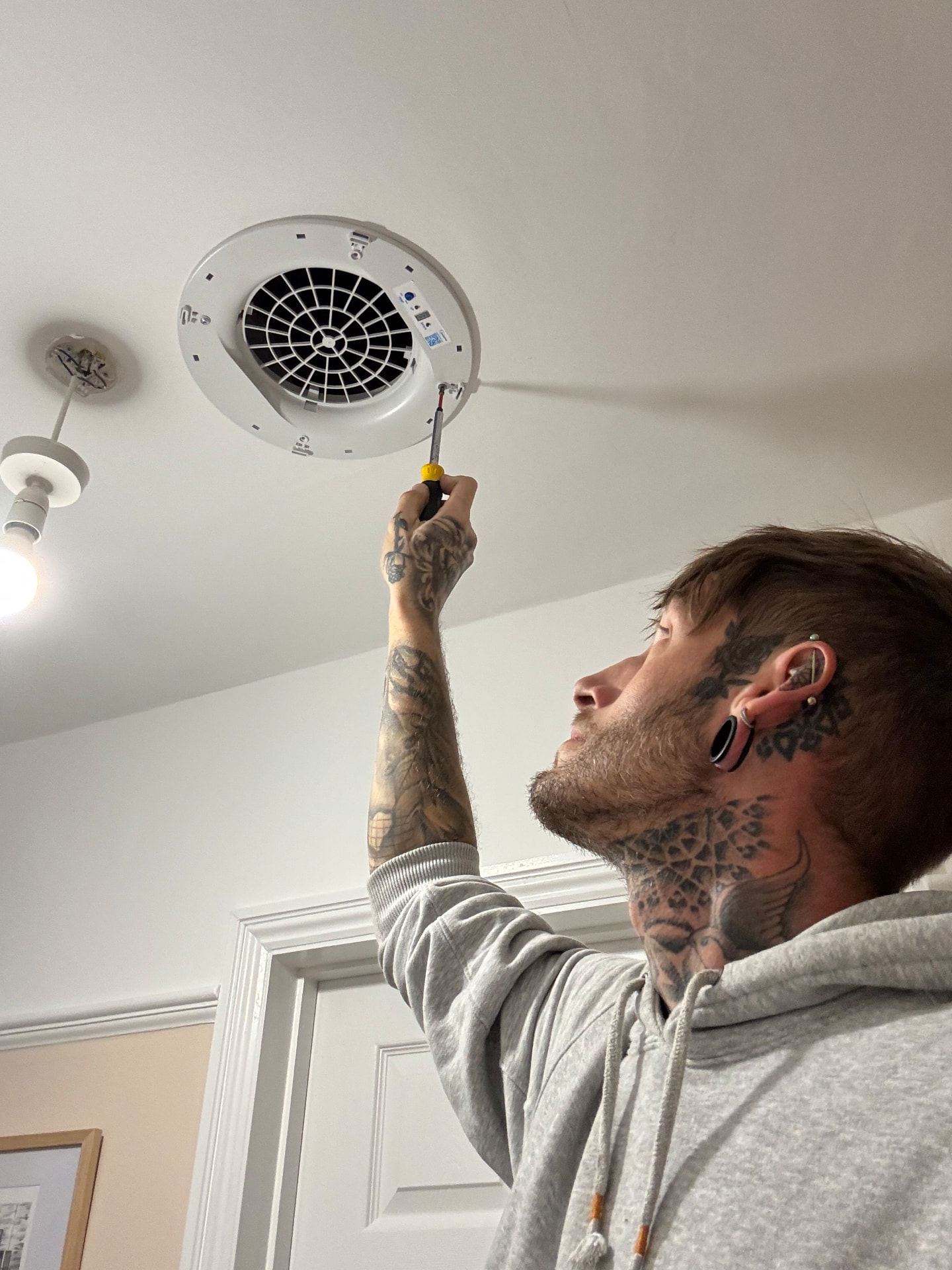
Fitting the ceiling diffuser
Installing the ceiling diffuser for a positive input ventilation system.
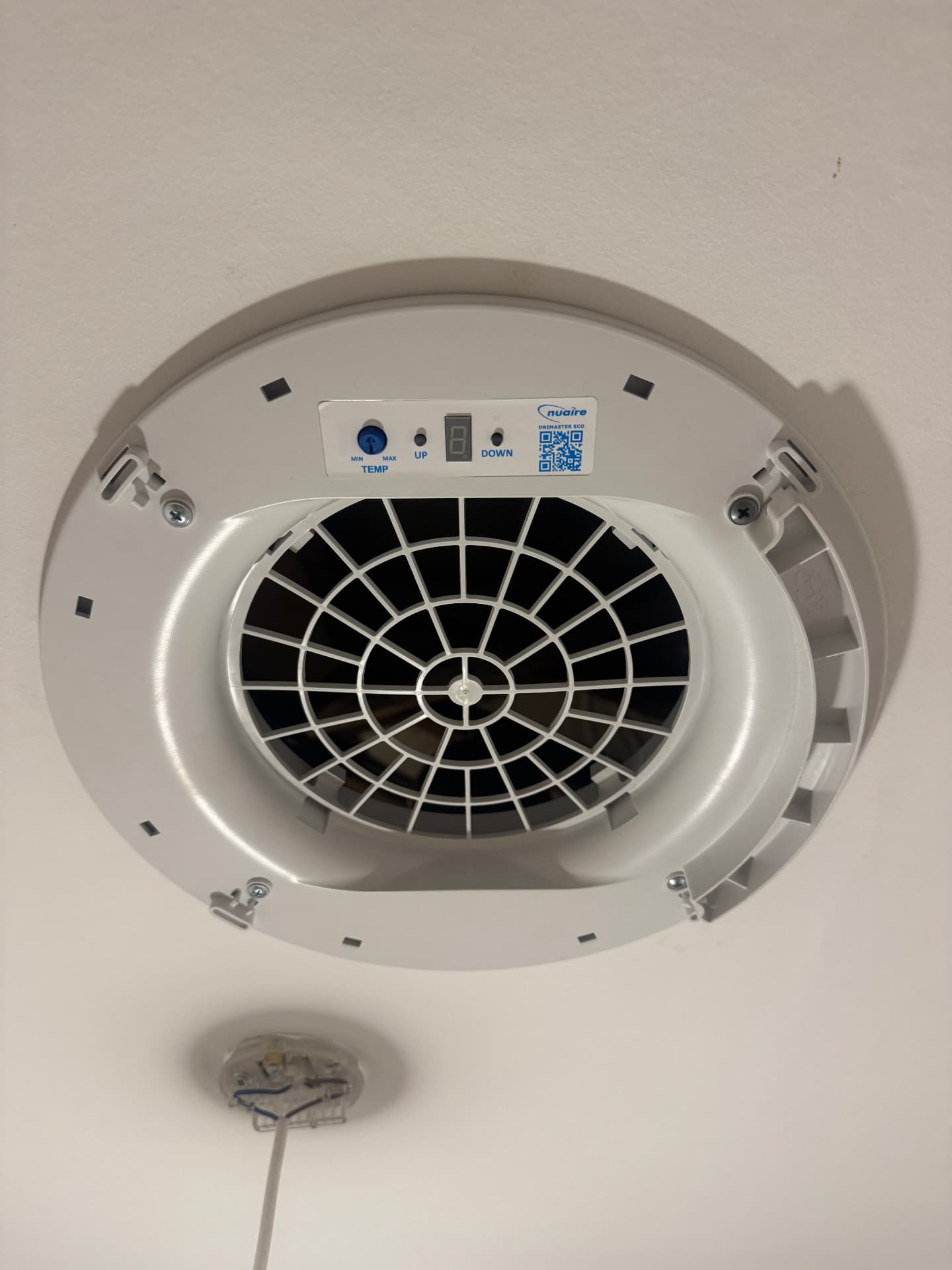
Diffuser fitted to the ceiling
Diffuser fixed in place before the cover is fitted.
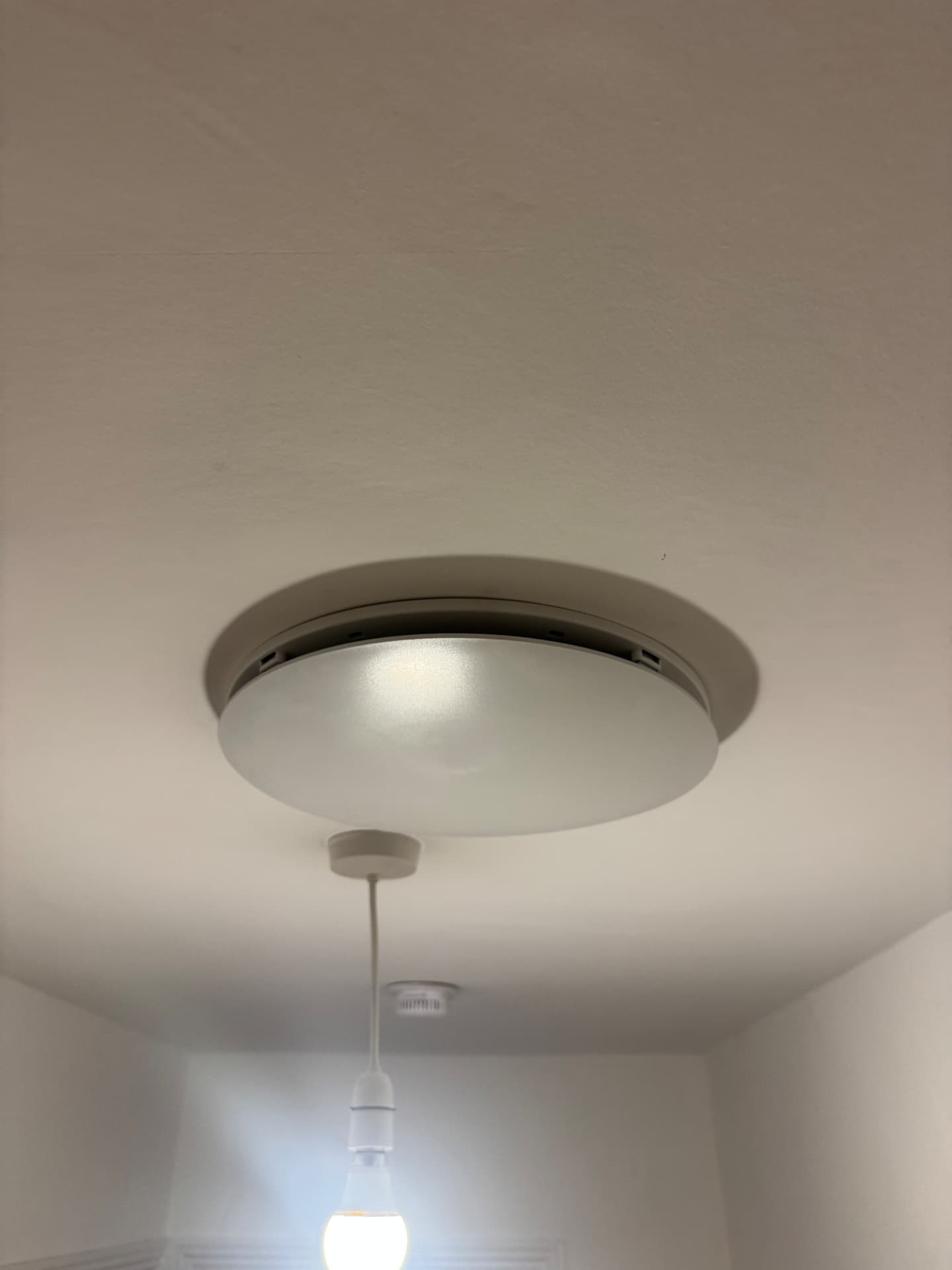
Finished ventilation diffuser
Completed positive input ventilation installation with a neat ceiling finish.
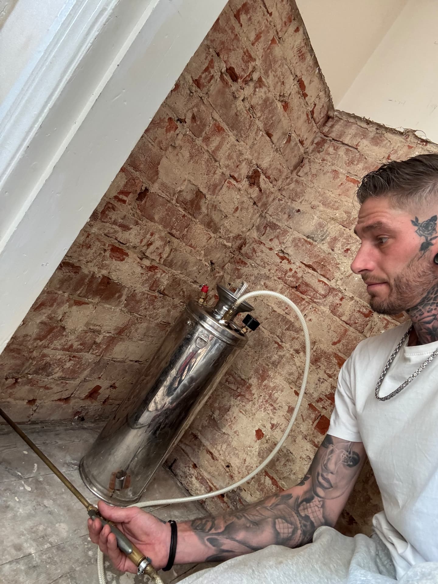
Damp proof course injection
Injecting a damp proof course into the brickwork to stop rising damp.
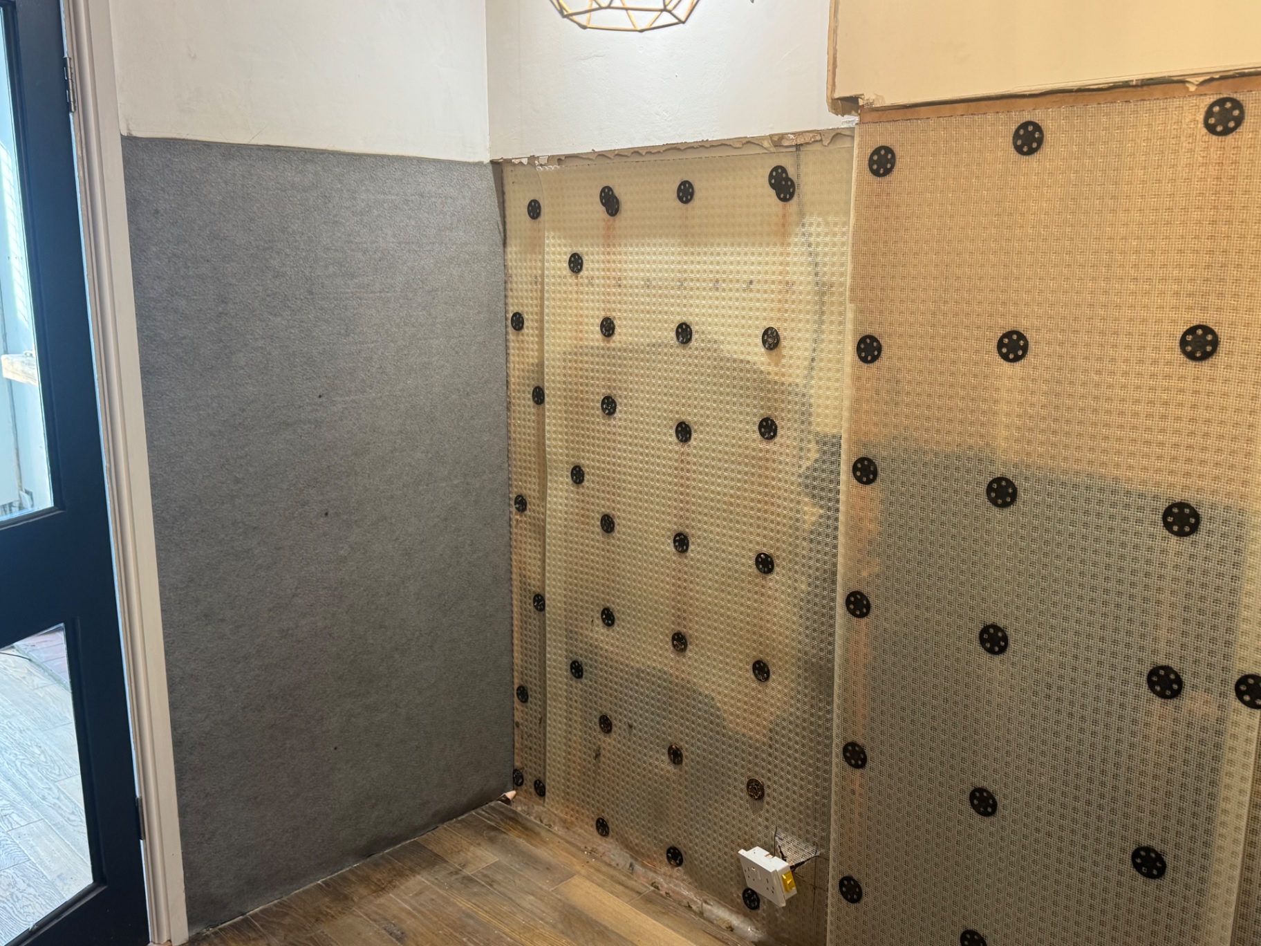
Damp membrane fixed to the walls
A cavity drain membrane mechanically fixed to a rising-damp affected wall around a chimney breast. The membrane separates the damp wall from the new finish so moisture can drain away harmlessly behind it.
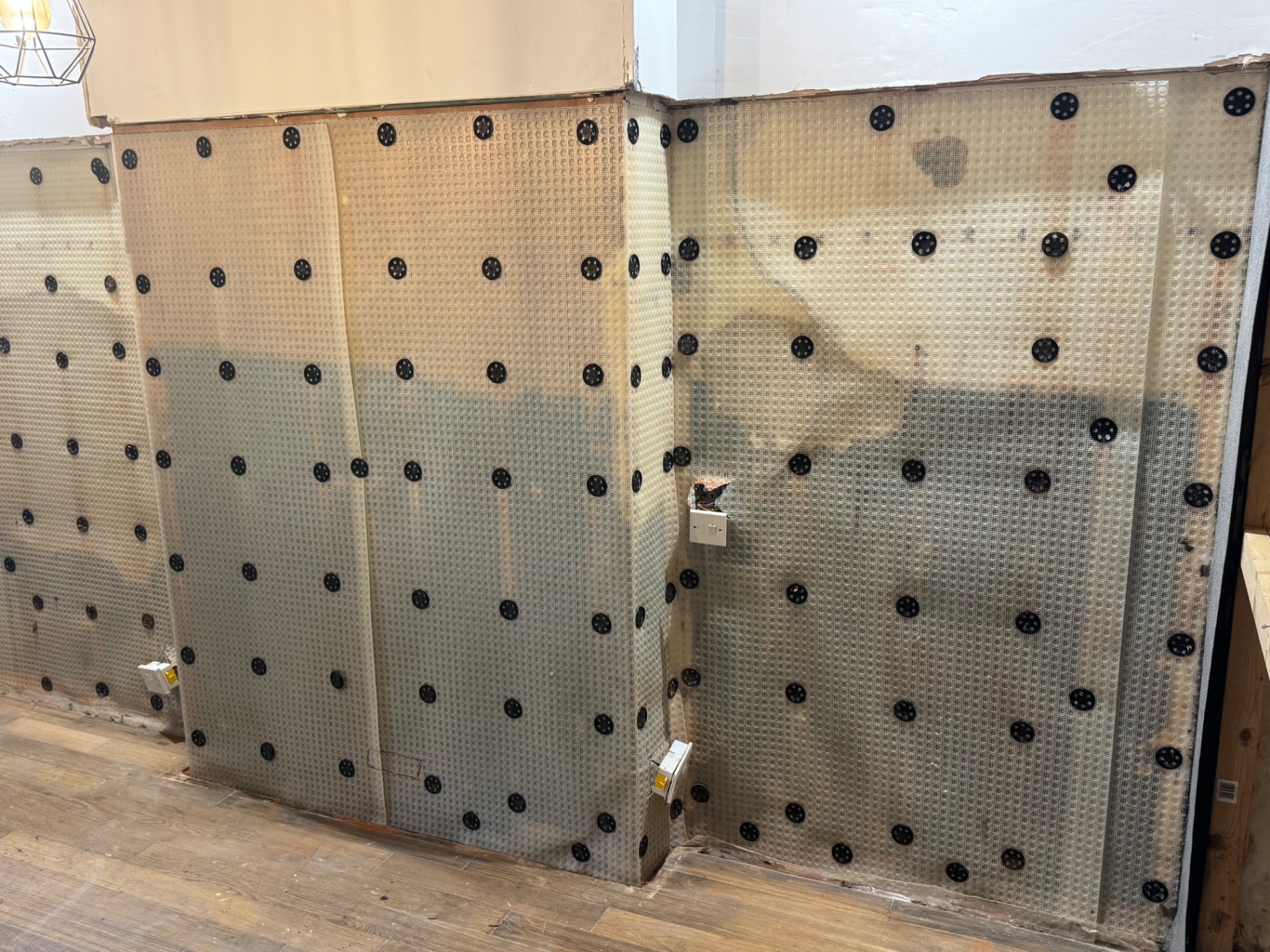
Membrane carried around every corner
The same installation taken around the chimney breast and into the room corners. Every socket and service point is cut in and sealed so the barrier behind stays continuous.
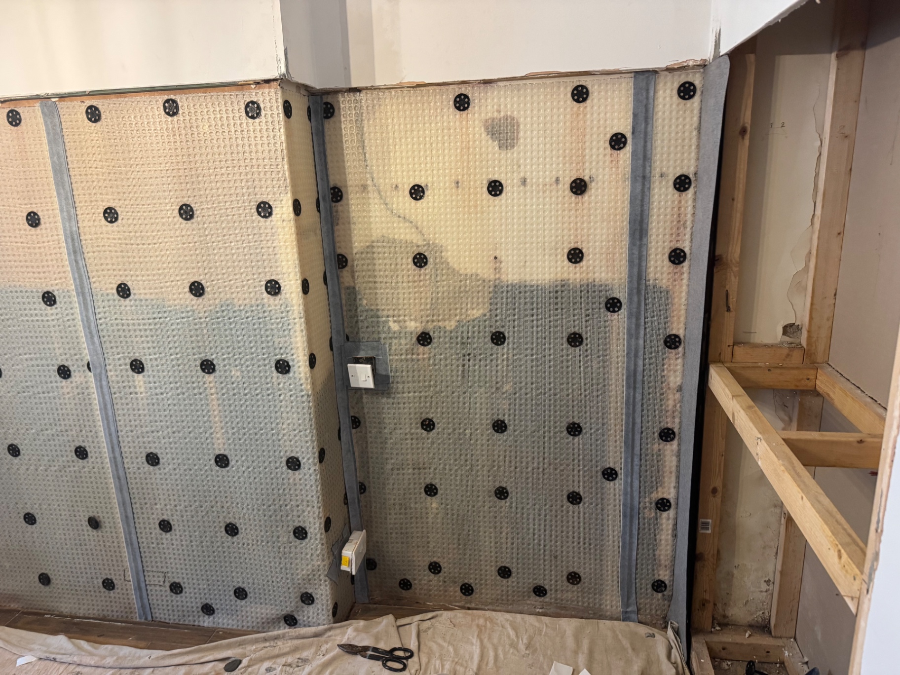
Sealed joints between membrane sheets
Where membrane sheets meet, the joints are sealed with jointing strip and rope so the cavity behind stays continuous. Getting this detail right is the difference between a system that works and one that fails.
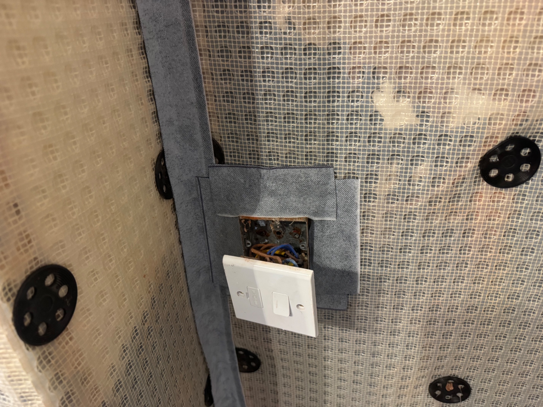
Socket box sealed into the membrane
Every electrical box is cut in by hand and sealed back to the membrane. Small details like this keep the waterproof barrier unbroken around the services in the wall.
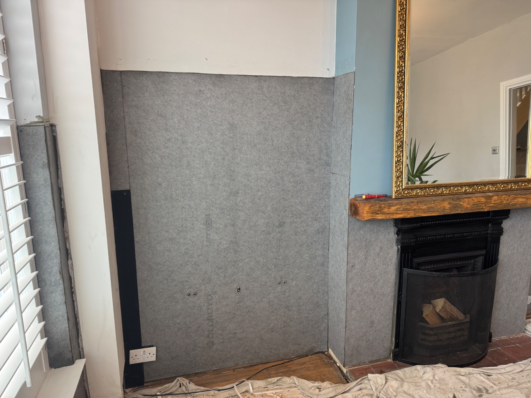
Insulated boards over the membrane
With the membrane complete, insulated plasterboard is fitted over it. This lifts the wall surface temperature too, which helps stop condensation forming on the finished wall.
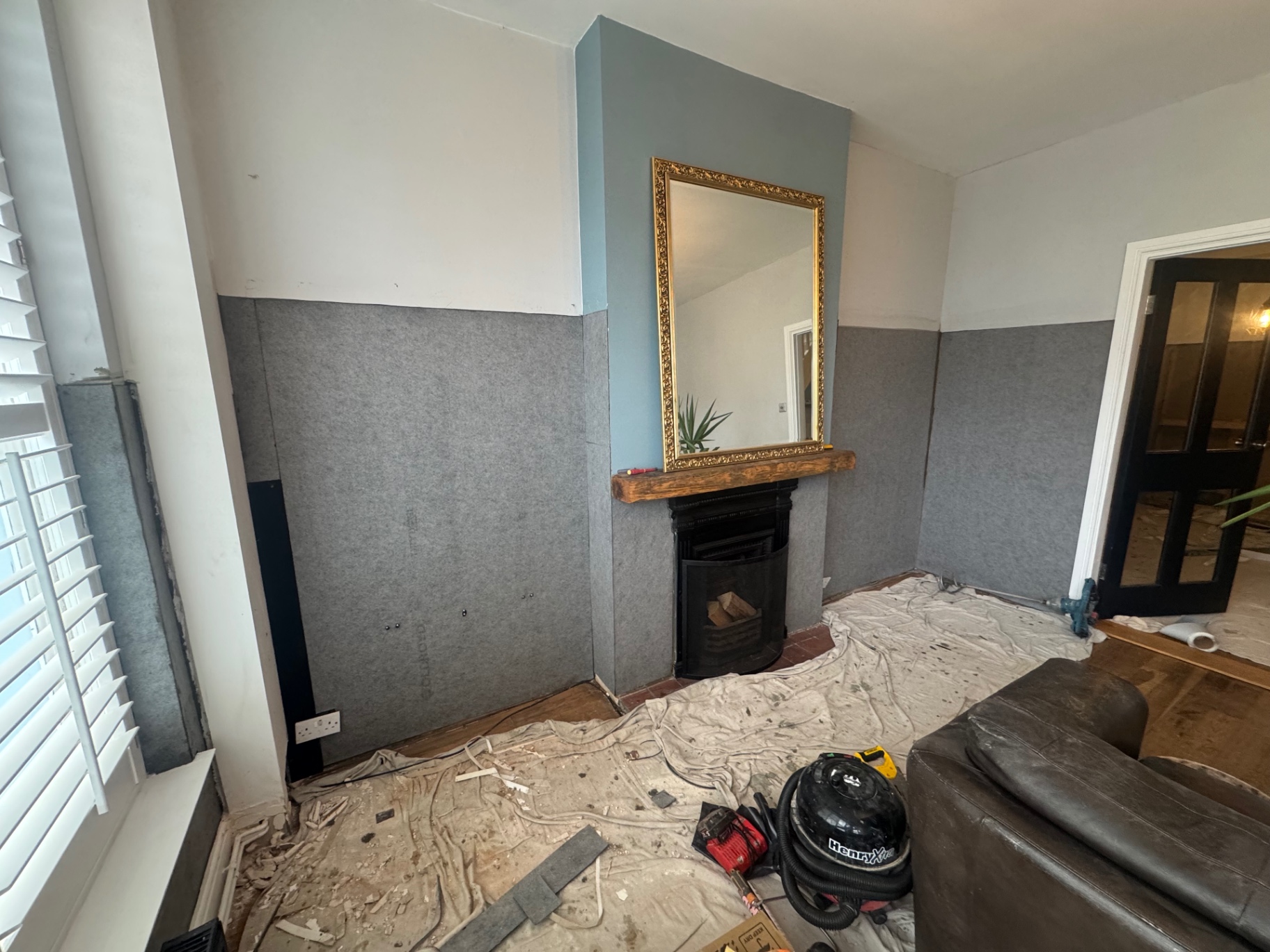
Full room ready for plastering
The whole room lined with membrane and insulated boards ahead of plastering. The chimney breast and both damp-affected walls are now isolated from the moisture in the masonry behind.
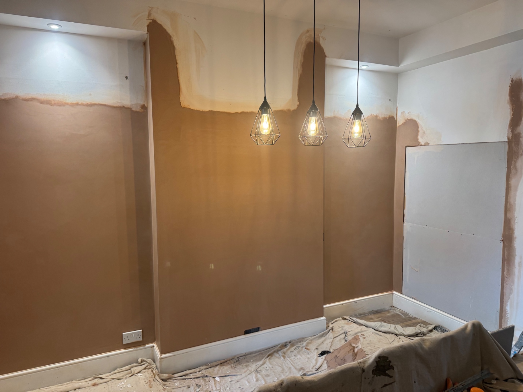
Renovating plaster applied
A salt-resistant renovating plaster skim finished over the system. It dries back to a normal painted finish — you would never know what is behind it.
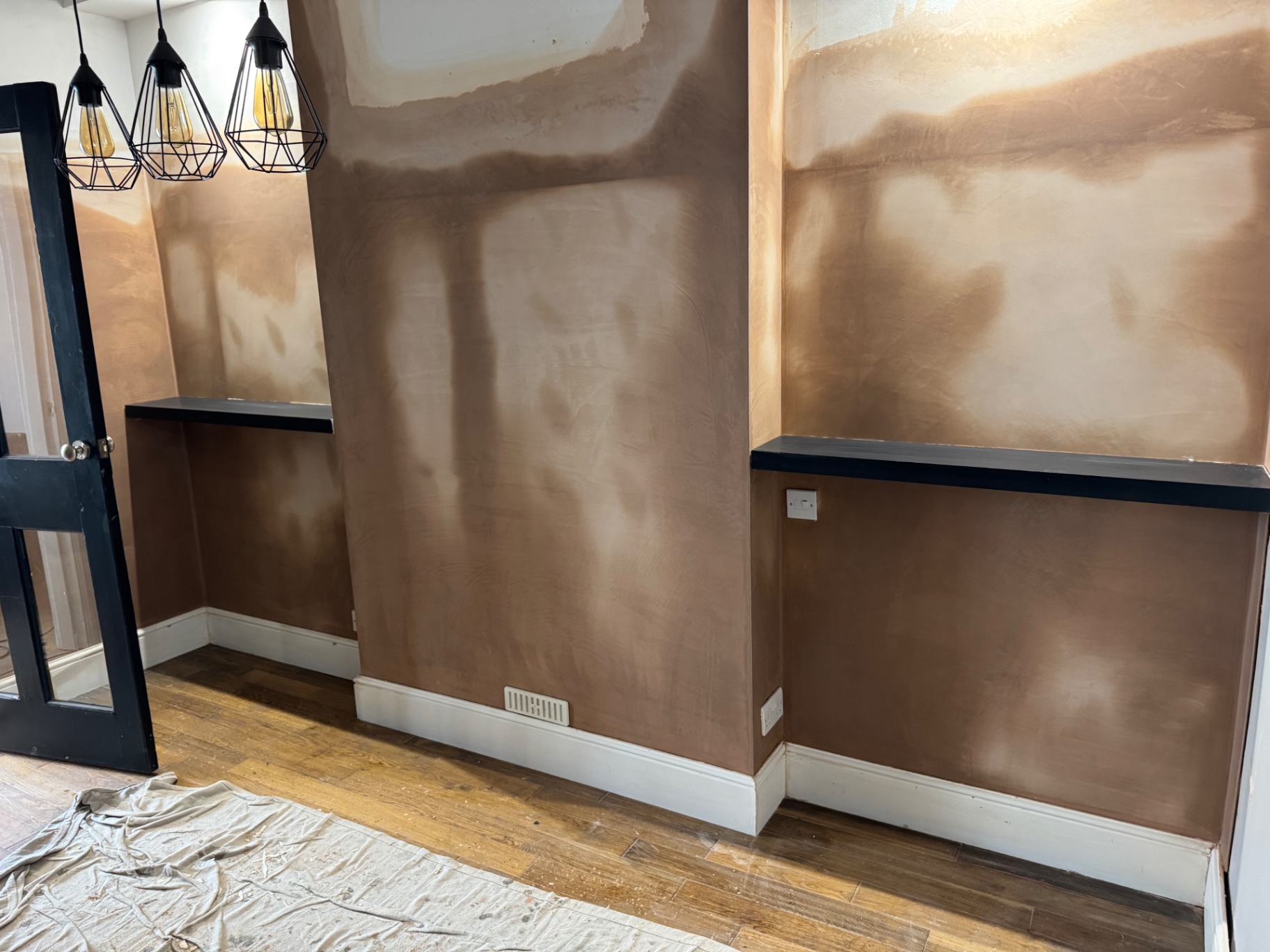
Finished walls with ventilation reinstated
The completed installation — smooth finished walls with the air bricks and ventilation paths reinstated at skirting level so the wall can keep breathing behind the new finish.
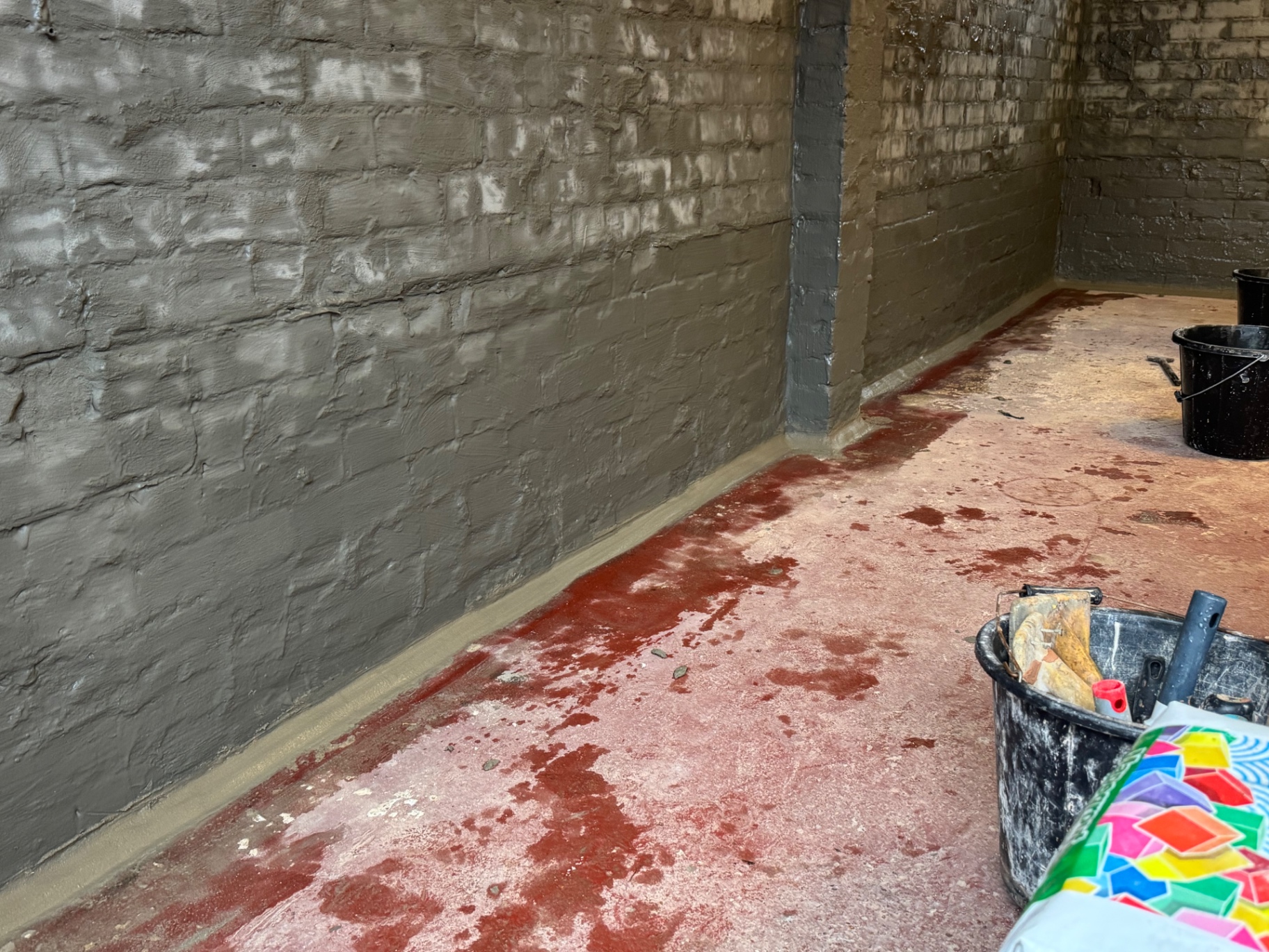
Type A tanking to the retaining walls
A flexible Type A cementitious tanking system rendered across the brick retaining walls of a garage. The render bonds directly to the masonry and holds back moisture entering through the retaining side of the walls.
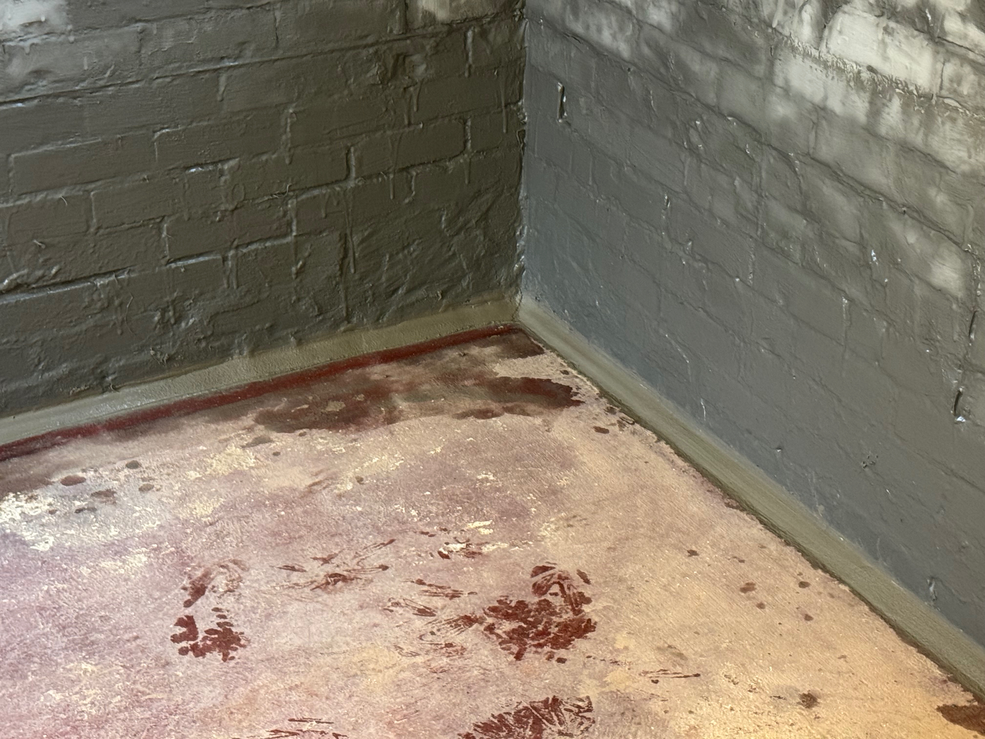
Flexible fillet seal at the wall and floor joint
The critical detail — a flexible fillet seal coved into the junction where the wall meets the floor. It lets the tanked surfaces move slightly without cracking, so the seal at the joint stays watertight.
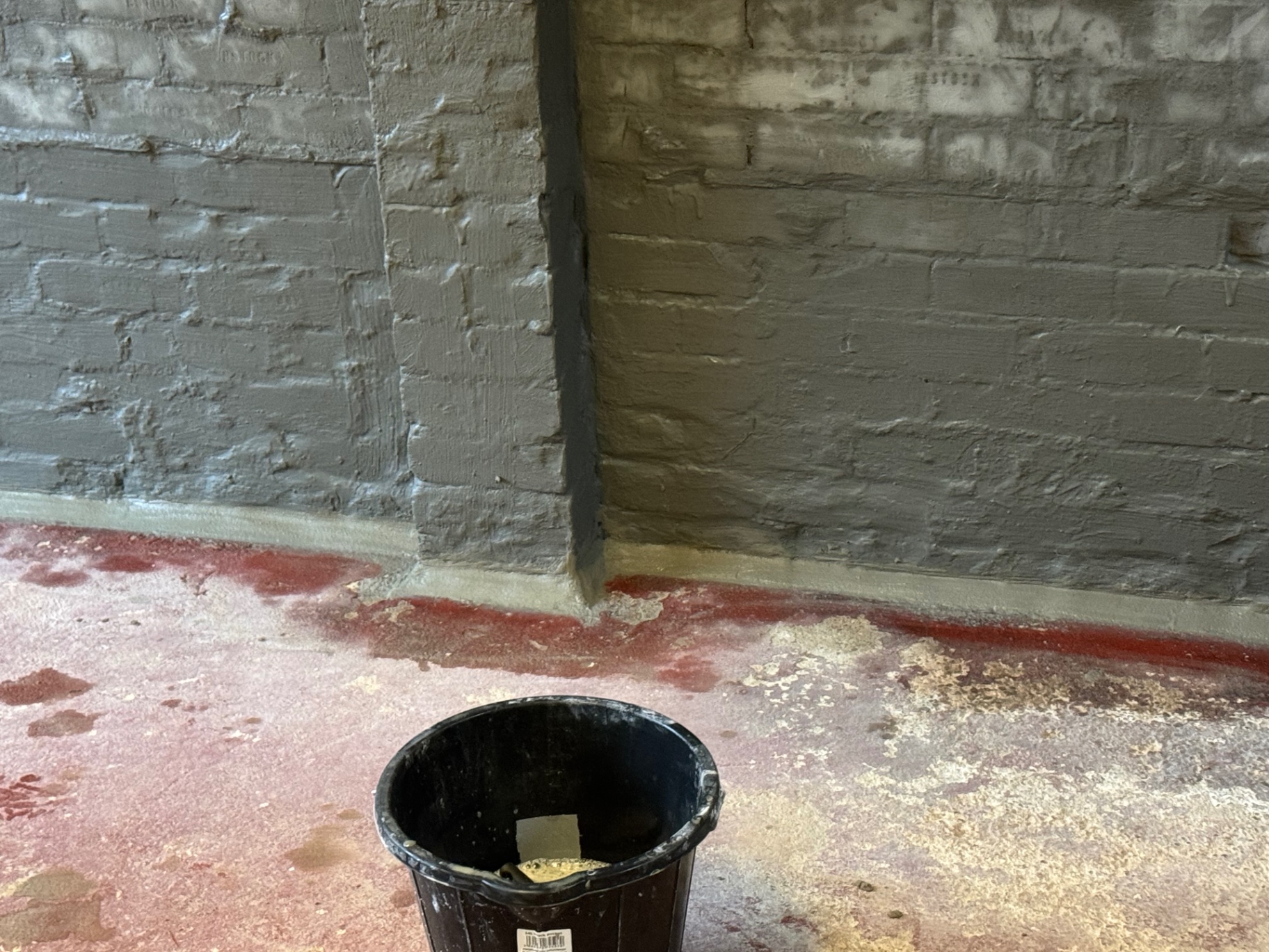
Fillet seal carried around every pier
The fillet seal is continued around piers, corners and buttresses — anywhere the wall and floor meet. Breaking the seal at a joint is the most common cause of tanking failures, so we form it continuously.
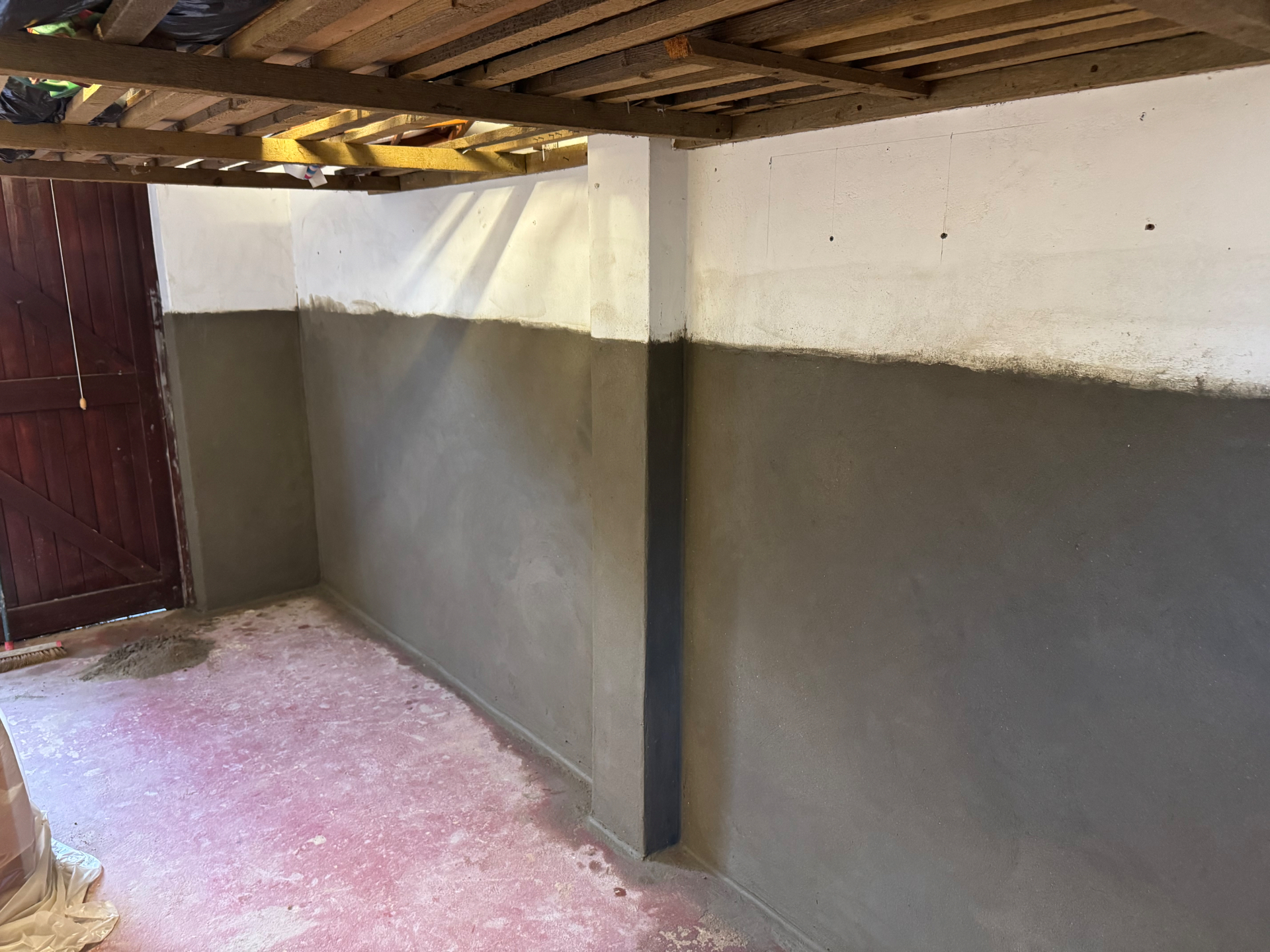
Tanked walls ready for the finish
The tanking render taken up the retaining walls under the timber floor above. The lower walls are now waterproofed — once cured, they're ready for the finishing render over the top.
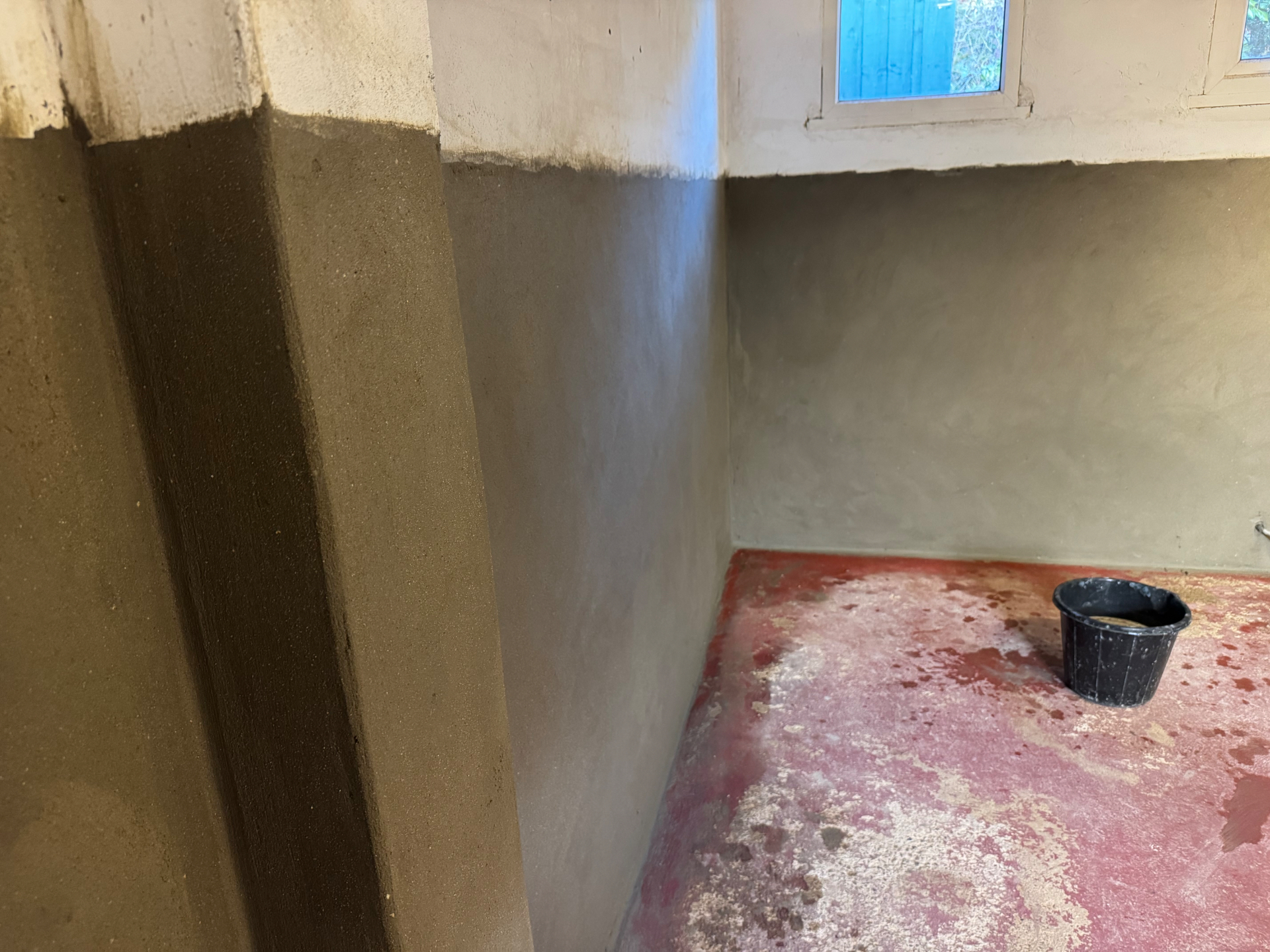
Tanking finished around the reveals
The system worked carefully around the window reveal and internal corners, keeping the tanking continuous across every change of plane in the wall.
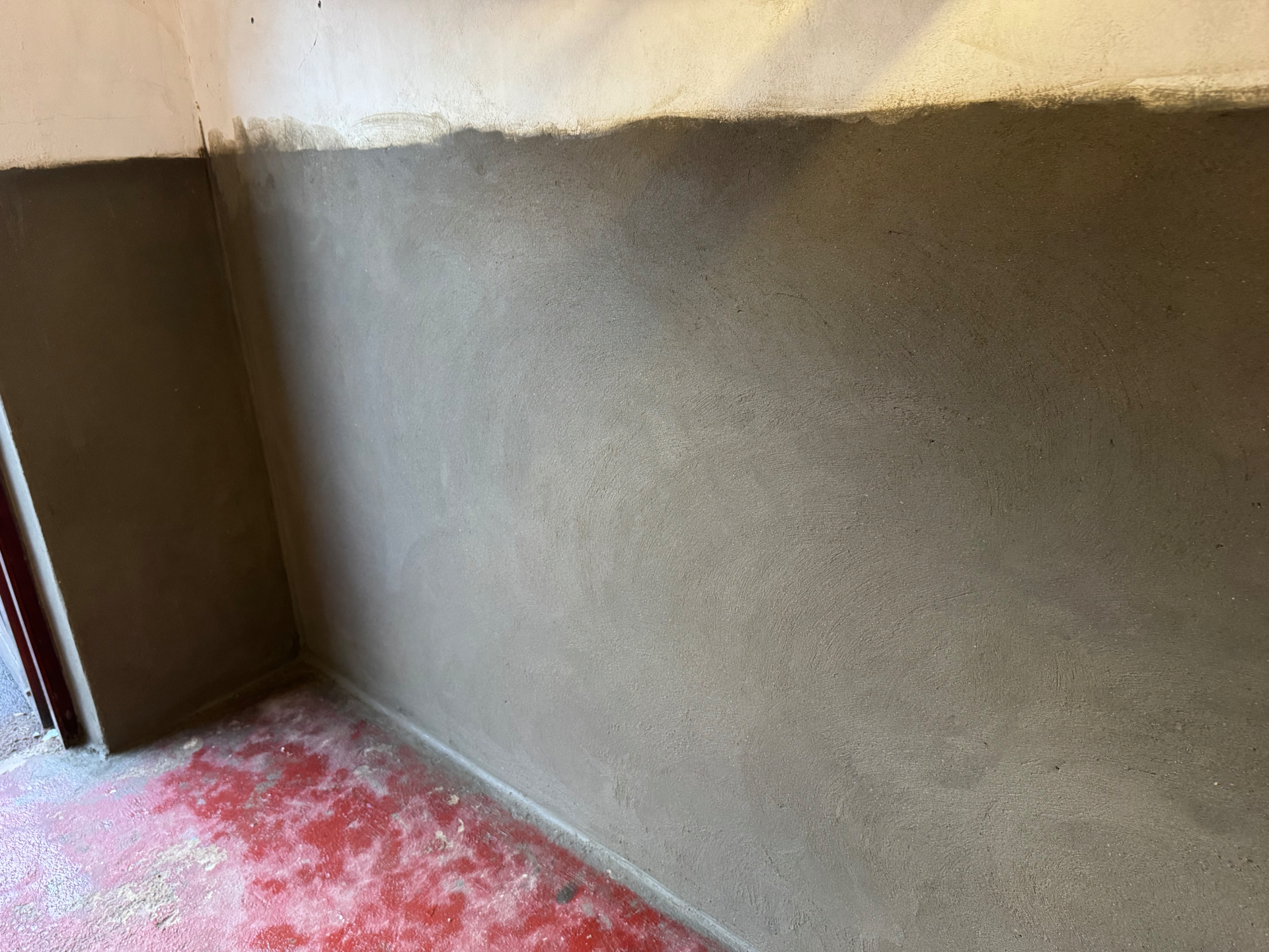
Render finish over the tanking
A smooth render finish applied over the cured Type A tanking. It gives a clean, paintable wall surface — the retaining walls are sealed and the room looks like any other finished space.
We add new photos as jobs complete — check back, or ask to see more examples from properties like yours when you get in touch.
Survey first, works second
Every installation starts with a survey
We survey first, diagnose the true cause, and only then quote for the works. That way you pay for the right fix — not a guess. All remedial works and installations are carried out by our own qualified team and fully guaranteed.
CSTDB & CSSW qualified · Experienced · Professional · Local · Trusted · All works guaranteed